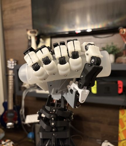
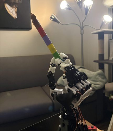
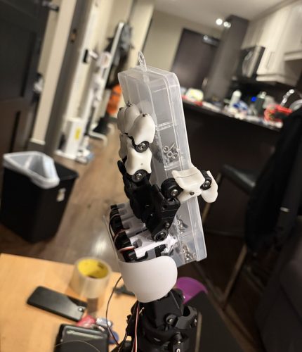
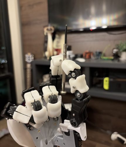
> the goal is to keep each tendon’s length independent of every other joint, keeping friction low, and keeping the whole hand serviceable.
ownership
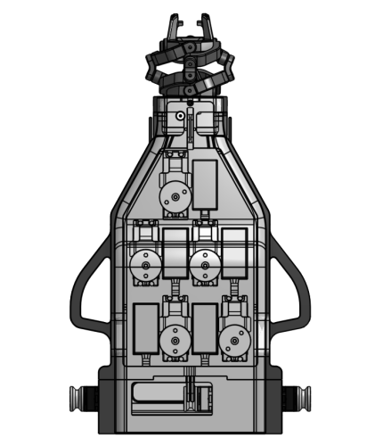
> everything between the servos and finger joints; spool sizing, tendon routing, servo packaging, power and electronic stack.
> I also designed the forearm shells.
Architecture
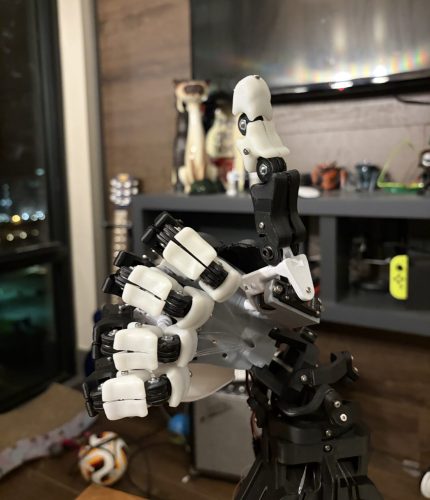
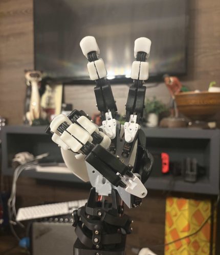
> Each finger couples its DIP and PIP joints and drives the MCP independently, with antagonistic tendons for flexion and extension. Abduction is driven directly by servos. Moving every actuator to the forearm keeps mass off the end of the arm and keeps motor heat out of the fingers.
> The tradeoff is that every tendon now needs a long path with low friction.
* three parameters that decided transmission accuracy: path length, spool size, friction, and tendon stretch.
path length
> Tendons pass through the center of each downstream joint axis, so bending one joint doesn’t change the length of tendons serving other joints. Every tendon passes through its center of rotation, so wrist motion doesn’t pull on the fingers.
Spool size
> Each flexor needs 7 mm of tendon pull. decided to use a 10 mm spool, which covers the stroke in ~80° of the 135° of usable rotation of the MG996R. 4.8 mm of extra pull to absorb tendon stretch and pretension. At 6 V, it gives about 216 N of tendon tension at stall, at a resolution of 0.087 mm of tendon per degree.
friction
> Tendon friction compounds with the total angle the tendon wraps through, following the capstan equation, T₂/T₁ = e^(μθ). A continuous PTFE tube guides each tendon from the wrist all the way to its servo, and I limited every turn along the path to under 15°.
> Why PTFE? PTFE has one of the lowest friction coefficients of any solid. Its static and dynamic friction are nearly equal, so the tendon slides smoothly instead of sticking and then jumping. That matters for position control at low speeds. A continuous tube also keeps the tendon off the printed parts. And it’s flexible enough to follow the forearm’s routing. I also considered a metal coil housing. I chose PTFE because it’s smoother, cheaper, and available off the shelf.
tendon stretch
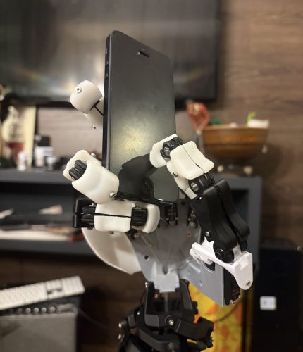
> The tendons are 0.18 mm braided PE line, which is UHMWPE fiber, rated at 20 lb (89 N). It stretches far less than regular nylon monofilament fishing wire, but over a 400 mm path it still stretches about 5 mm at a 30 N grasp load. More than the 4.8 mm of spare pull the 10 mm spool provides, so a finger loses a fraction of a mm of travel under full load. Since position error grows with load, we decided to integrate the fingertip FSRs to close the loop on force.